|
Old Computer-related pictures and photos
 Picture 4 of 26 Picture 4 of 26  |
|
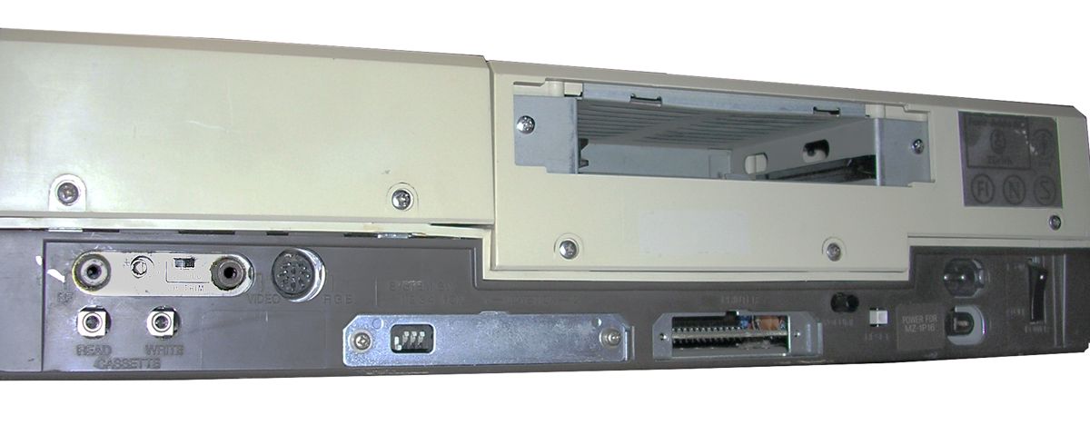
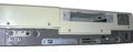
Rear: RF output, channel trimer, BW/COlor/ switch, composite o/p,
RGB o/p. Below are cassette i/o jack. Next system DIP switches,
2 Joystick connectors (covered with plate), printer port, volume
knob, reset switch, AC in and DC out below (to printer), ends
with power switch. In upper half expansion bay. |
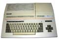
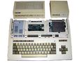
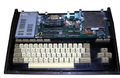
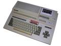
General View
|
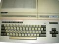
Keyboard detail
|
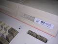
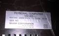
Front sticker
|
Rear: RF output, channel trimer, BW/COlor/ switch, composite o/p,
RGB o/p. Below are cassette i/o jack. Next system DIP switches,
2 Joystick connectors (covered with plate), printer port, volume
knob, reset switch, AC in and DC out below (to printer), ends
with power switch. In upper half expansion bay.
|
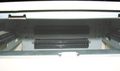
Expansion bay inside - 2 slots.
|
Back sticker
|
Peripheral covers removed. Internal tape recorder is connected to
the white connector on the left of RF modulator can
(here bridged with 3 blue/black wires).
|
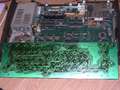
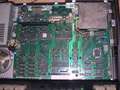
Inside
|
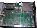
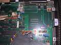
Mainboard general view
|
Memory. Notice quite good speaker.
|
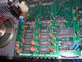
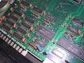
CPU, ROM and parallel I/O chips.
|
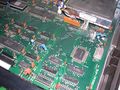
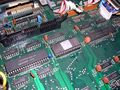
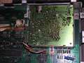
PLA, video RAM expansion sockets (two 16k*4 DRAM goes here),
8255 parallel circuit
|
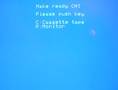
Boot screen
|

Monitor program
|
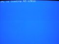
Loading BASIC...
|
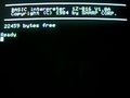
Basic itself.
|
MZ-821: General view
|
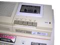
MZ-821: Tape recorder
|
MZ-821: Tape recorder isnide
|
MZ-821: Place for cassette
|
MZ-821: Keyboard PCB
|
MZ-821: Memory is from different manufacturer
|
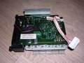
MZ-821: Mainboard
|
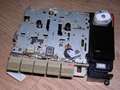
MZ-821: Modulator PCB
|
MZ-821: Under the modulator
|
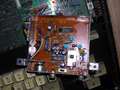
MZ-821: Modulator components
|
 · ·  · 1 · · 1 ·  · ·  |
|
|
Gallery generated by SPGM, Terminal theme by MCbx. |
All pictures are:  . .
|
